


C5 Heads/Cam Swap
E-mail jmX with corrections
Click here for a printable version
| Tools Needed: |
- Set of metric sockets, deep and normal (from 8mm to 19mm is good) - Set of Metric wrenches (8mm, 10mm, 13mm, 15mm, 18mm, 19mm) - Metric "Gear" wrenches (not absolutely necessary, but REALLY handy) - 18mm FLAIR NUT wrench - 8mm hex allen wrench - T-40 Torx bit - Torque wrench for 20lb/ft up to 150+lb/ft - Various socket extensions, ranging from 3" to 12" - Medium length socket wrench - Large 1/2" drive breaker bar - Piece of pipe to slip over breaker bar handle - 1/2" drive 24mm socket - Adapter from 1/2" drive to 3/8" drive - 3 armed pulley puller - Felt tipped marker (if using stock headbolts) - Plastic ice scraper - Prybar or large flathead screwdriver - Medium sized pliers (for hose clamps) - Medium sized flat head screwdriver - 3/8" fuel line disconnect tool - 3+ gallon Bucket - Optional: Flywheel locking tool (for automatic transmission cars only) - Optional: Longer crankshaft pulley bolt (Size specs coming soon) |
| Parts/supplies you will need: |
Parts: - 2 LS1/LS6 engine heads - 1 Camshaft - Optional: Underdrive crank pulley - Optional: blueprinted oil pump - Optional: New timing chain - Optional: New OEM 2001 style intake manifold Bolts/gaskets: - 2 GM headbolt kits (2x GMPN 12498545) - OR ARP head bolts or head studs - For 97-01' style heads, buy 1 pair of headgaskets (1x GMPN 12498543) - For 02-03' style heads, buy 1 pair of headgaskets (1x GMPN 12498544) - 2 AIR tube gaskets (2x GMPN 12553617) - 2 Water pump gaskets for 1997-98 model cars (2x GMPN 12559271) - 1 front engine seal (1x GMPN 12561244) Supplies: - 7 quarts of oil - new oil filter - Jug of dexcool compatible coolant - RTV Hightemp silicon gasket maker - Locktite (red tube) - Tube of Anti-seize - Shop rags, roll of paper towels - One can of compressed air with plastic straw (look in computer section of an electronics store) |
Preface
|
Like many others, you are looking for more horsepower. The only real obstacle keeping us from the horsepower we want is money. So, to save money and put it towards more parts, I decided to do my own labor. You'll be surprised how easy most of the install is, and you may also be surprised just how much stuff there is to do! During this install, I'll be putting the following items onto my 1999 Corvette Coupe. Many of these items are optional, but most of the labor isn't (meaning, you might as well replace this stuff while you are in there since you'll be taking it off anyway). - GTP Stage 2 LS1 Cylinder heads, purchased from Thunder Racing - Thunder Racing 227/224 "reverse split" camshaft, purchased from Thunder Racing Optionally, I'm installing - Katech ported oil pump, available from Katech or Thunder Racing - JWIS Timing chain purchased from Thunder Racing - ASP underdrive pulley, purchased from MTI If you still have the stock 97-00 intake manifold on there, now is a good time to put the 2001+ version on. Only 15-20 minutes of additional labor is needed. |
Pictures of the parts:

|
All the parts you should have bought, plus optional stuff. Heads, cam, timing chain, underdrive pulley, new oil pump, ARP head bolts, and some gaskets. |

|
Pics of double springs (more reliable than standard single valve springs). The springs pictured (Comp 987) will require head modification to the spring seats to allow space for them to fit. Thunder Racing had this done to my set of heads for extra reliability. |

|
This is what a ported intake port looks like. This is a 5.7L LS1 style head casting. |

|
This is what a ported exhaust port looks like. This is a 5.7L LS1 style head casting. |
Lets begin:
|
PART 1: Removal of the steering system Time to complete: 2-6 hours |

|
First get the front end of your corvette in the air. Drive it on ramps, set the steering wheel at dead center (wheels pointed straight ahead), then shut the car off and loosen the front wheel lugnuts. Chock the rear wheels with some wood/rocks/wheel chocks/whatever, and jack up the front via the metal crossmember in the center and place 2 jack stands under the crossmember, one on each side of the jack, spacing them about 2 feet apart from each other and making sure they are SOLIDLY placed on the crossmember (don't want the car to slide off!) when you lower the jack. Now Remove the front wheels. Pop the hood and disconnect the ground cable going to the battery, and remove the cap to the coolant reservoir. Grab a bucket and place it under the petcock valve on the passenger side of the radiator. Open the valve using an allen wrench or a large flat head screwdriver by turning it counter clockwise. As the coolant drains into the bucket, continue on with the next step. |

|
Using a flathead screwdriver untighten the clamp where the intake duct meets the throttle body. Disconnect the IAT wire going to your air coupler and the MAF wire going to your MAF. Disconnect rubber AIR hose from airbox or aftermarket air assembly (its down in front right near where the bottom of the hood is). Remove the air cleaner/maf assembly from the car. |

|
Using a 15mm socket wrench or 15mm wrench on the drive belt tensioner, relieve the pressure on the drivebelt and slide the belt off the water pump. Release the tensioner and unroute the belt as much as you can (it can stay wedged in the engine bay for now and we'll remove it totally once we get further along). |

|
Disconnect the PCV rubber hose going to the throttle body on the passenger side. Unclip the 2 electric connectors going to the throttle body (one on each side of the TB). If you haven't done the TB Bypass mod, grab a pair of pliers and remove the 2 rubber coolant hoses going to the throttle body. Then, using a 10mm socket and 3" extension, unbolt the 3 bolts holding the throttle body to the intake manifold and remove the TB. |

|
Using a pair of pliers, now slide the spring clamps off the 4 hoses that go to the water pump. There will be 2 smaller hoses going into the passenger side of the pump, 1 big one going to the passenger side of the pump, and one big one going in towards the center of the water pump. Once the clamps are all slid back some, pull or pry (using a large flathead screwdriver) the hoses off the pump. Coolant will most likely start pouring out of some of these....you can try to catch some of it in a bucket but I usually just let it hit the ground. Now, there are 6 10mm bolts that hold the pump to the block, 3 on each side. See diagram of the pump on the left for their locations. Unbolt all 6 bolts and remove the water pump from the car. Coolant again will start leaking once you loosen all the bolts, its inevitable. Don't worry about it. |

|
This part is tricky. We need to remove the radiator. First unbolt the plastic radiator shroud, it is held to the frame by 2 10mm bolts on each side of the car. Next, get under the car with a small flathead screwdriver and unclip both fan electrical connectors (using the flathead screwdriver, as its impossible to do with your fingers), and unclip all the wiring rings holding the wiring harness to the fan shroud. You're all done under here, go ahead and get back up to the top of the engine bay and grab a friend to help with the next part. Now, you have a big assembly here....the fan shroud is mounted on the radiator via 4 slide in tabs, and on the front of the radiator the AC condenser (looks like another radiator) is attached to the radiator with 4 tabs. We need to slide the AC condenser UP about 2 inches to dislodge the tabs and get the radiator free from its grasp. This will take some cursing and a good light source so you can see the 4 slide in tabs I'm talking about. Once the AC condenser is loose from the radiator, both of you need to lift the radiator up and out. Lifting the radiator up and out....that sounds so easy doesn't it? HA! This part can sometimes be frustrating, so be patient. While trying to remove the radiator, you'll need to make sure that on the drivers side you dont catch on the AC condenser hard lines, as well as a HUGE wiring harness that runs real close to the radiator. The large coolant hose will want to snag on it. Keep wresting with it until the radiator/fan assembly comes out totally, and set it aside. The AC condenser will stay in the car for the whole install. NOTE: in the pic on the left, I have my fan shroud and radiator separated for cleaning purposes. |

|
Disconnect the electrical connector going to the alternator and using a 13mm socket unbolt the power cable off the back of the alternator. Using a 15mm socket wrench, unbolt the 2 bolts holding the alternator onto the accessory bracket and remove the alternator from the car. Now get under the car and unbolt the two plastic powersteering cooler line brackets from the front of the crossmember. While we're down here, lets also disconnect the swaybar from the endlinks at the far ends of the swaybar. This takes a 18mm box or gear wrench and a t-45 torx bit/ratchet. NOTE: it doesnt matter which end of the endlinks you disconnect, but some have found its easier to unbolt the end that mounts to the suspension A-arm rather than the end that connects to the swaybar. Once both endlinks are disconnected, get under the car and use a 15mm socket wrench to remove the 2 metal brackets that hold the rubber swaybar bushings and swaybar in place. There are 2 bolts on each bracket, with one bracket on each side of the car. Once the 2 endlinks are disconnected and the two brackets are removed, the swaybar will be free from the car and can be removed from the car. |

|
Now, look down in the drivers side of the engine bay at the steering rack and you'll see 2 metal lines going into the gearbox on the steering rack. Using an 18mm flair nut wrench, unbolt both of these lines. Have a roll of paper towels ready as some power steering fluid will seep from these. |

|
With the PS cooler line unbolted and the 2 lines to the power steering gearbox undone, we're now ready to unbolt our powersteering pump bracket and remove the whole assembly from the car. Using an open ended 15mm wrench, find the 4 15mm bolts that are bolting the bracket to the head. This part will take a little patience as a few of the bolts will only be able to be turned a few degrees each time. The important thing to remember for those hard to turn bolts is to unbolt them all at the same time, a little bit at a time. You'll see what I mean when you get there. This whole process should take about 10 minutes. |

|
Once all 4 bolts are out, you should be able to pull the whole assembly out of the engine bay, with the powersteering cooler line still attached. When you store this assembly lay it so the fluid doesn't leak out of the lines if possible. |

|
Now, if the steering wheel is straight you should have a good angle to get to the 13mm bolt. If the plastic boot is obscuring access to it, use a flathead screwdriver to to loosen the clamp and slide the boot upwards. If for some reason you don't have clear access, turn the steering wheel until you have access (if you have a column lock bypass you can do this without the battery connected, otherwise reconnect the battery and turn the wheel). Once you have access to the bolt, use 12-18" worth of extensions and a 13mm socket to unbolt the linkage bolt at the bottom. Once the bolt is out, put the steering wheel at the centered position and make sure both your front rotors are pointing straight ahead (this just makes things easier later).
Now slide the steering shaft sideways off of the gear box stub, it may or may not be easy. I've worked on 2 C5's and one required ZERO effort to slide off, the other required a prybar and a hammer. The important thing to remember when working with the C5's steering setup is that once we disconnect this shaft, we need to NOT move the steering wheel to be extra safe that we don't damage anything after we get it all back together. It will also make sure the steering wheel is lined up properly rather than being off center (we can be off by 180 degree increments). If the shaft simply isn't coming off, try to spray some lube like WD-40...its just a slip fit on and the bolt is what clamps the slip connector onto the rack connector. If it still isn't coming off, just leave it connected for now and there may be a better opportunity to remove it in a little while once we start moving the whole rack around (ie, you may have more space to swing a hammer then). |

|
Grab a deep 18mm socket wrench or box wrench and unbolt the 18mm nut where the tie rod end connects to the wheel spindle. Once the nut is off the threaded shaft, take a hammer and whack the tip of the threaded shaft downwards to dislodge it from the spindle. Some people have reported that they didn't need to use a hammer at all as their tie rod ends fell right out once the nut was removed. Others (again, like me) had to whack it with a hammer a few times before it popped out. Repeat steps for the other side of the vehicle. The rotors will now turn freely. |
|
|
By now you should have disconnected the following things. 1) The two hydraulic lines going to the powersteering gear box 2) The intermediate steering shaft 3) The 2 tierod ends Now the only thing holding our powersteering rack in are 2 18mm bolts and one electrical connector. Get under the front of the car and look at the crossmember. You'll see 2 18mm bolts going into the crossmember holding the rack on. You'll need an 18mm socket and an 18mm wrench for the nut on the other side. These are easiest to remove when a person from above can hold the nut with the wrench, and the person below can ratchet on them. On the drivers side you'll notice there is an aluminum bracket holding up the ABS controller block. Unbolt the 4 bolts holding this to the crossmember as well, as we'll need to wiggle the ABS stuff out of the way soon. If you undo the 3 10mm nuts at the top of the bracket that hold the block on, you can totally remove the bracket from the car. This is recommended if you find you don't have enough clearance (you'll find out soon). Now, one last thing...disconnect the electrical connector going to your power steering box. Active handling cars have this for sure, other models may or may not have it. It is for the sensor that detects the direction of the vehicle. |

|
FINALLY, Lets get this rack outta here! The goal here is to get the power steering rack sticking out of the passenger side wheel well. We are going to lift the rack up about 2 inches, then rotate and slide the whole thing over about 2-3 feet. So, first, using a large screwdriver or prybar, get the rack unseated from the crossmember. One side will have a rubber bushing, the other probably will just be a metal to metal connection and wont be tough. Once its up as far as it'll go, spin the rack until the tabs that were attached to the crossmember aren't in the way of the crossmember, and start moving the whole piece out through the passenger wheel well. The steering rack gearbox may conflict with the engine crank pulley, so rotate the rack until the gearbox is pointing towards the front of the car and continue sliding it out until it'll go no further. It should be out as much as the picture provided on the left. Pat yourself on the back, part 1 is complete! |
|
Part 1 Complete
You have now successfully removed the steering system from your corvette! This was necessary as to get the camshaft out, we need to pull off the timing cover, which means pulling off the crankshaft pulley (Step 4 will cover this)...which means the steering rack has to get out of the way. Next we'll start working on removing the heads and later we'll come back to removing the cam. I put this step first because if you can get the steering rack out, you should be able to pretty much handle anything from this point on. |
|
Part 2: Removing the Intake and Exhaust Time to complete: 2-6 hours |

|
On each side of the engine, there is a metal AIR tube bolted onto the exhaust manifold or header. Each is held onto the exhaust by 2 10mm bolts. Remove them. On the drivers side, the AIR tube immediately connects to a rubber hose. Using a flathead screwdriver, undo the plastic clamp on the rubber hose and remove the AIR tube totally from the engine bay. On the passenger side, this will not be possible. While on the passenger side of the car, using a 10mm wrench to unbolt the oil dipstick tube from the exhaust manifold and with a firm tug, pull the dipstick tube up and out of the engine bay. |

|
Now disconnect all 8 plugwires from the coilpacks. Try not to pull on the wire, but instead pull on the boot that connects to the coil. Next, disconnect the wiring harness that goes to the coilpacks. Its a large white weatherpack connector, labeled in the photo. Next we need to remove the coil packs from each valvecover. On 97-98 LS1's, each coil pack is bolted to the valve cover separately. On 99+ year models, all the coil packs are on a bracket and the bracket is then mounted to the valvecover. Depending on your year, either unbolt all the coil packs individually (97-98), or unbolt the 5 10mm double-ended bolts (using a deep socket) and remove the coil bracket with coils still attached. On 99+ year model cars, there may or may not be a bracket mounted to the backmost bolt. If there is, undo the nut and pry the bracket off with a big flathead screwdriver, and then unbolt the final bolt to remove the coilpack rail. |

|
Now that we've got the ignition disconnected, lets take care of the fuel system. On each fuel injector on the intake manifold, you'll see a metal clip on the bottom of the connector. You need to push this metal clip in and compress it, then pull the electrical connector off of the injector. Some of them will be tough, while others are easy. Disconnect all 8. Next, unscrew the fuel pressure test port cap on the tip of the drivers side of the fuel rail. Grab a big rag and a phillips screwdriver, and while surrounding the testport with the rag (incase of high pressure spray!), press in the schraeder valve (like on a tire) to relieve any fuel pressure that may be left. Chances are nothing will spray out since the car has been off so long, but its better to be safe than sorry. Now, get your 3/8th inch fuel line disconnect tool and put it around the hard metal line coming off the fuel rail. This tool will slip under the connector on the braided steel fuel line and that will undo the metal tangs that hold it onto the fuel rail. See photo for clarification. Swing fuel line out of the way and have rags handy to catch all the fuel that will be spilling out of the fuel rail. |

|
In the rear drivers side of the engine bay, you'll see a big black metal brake booster that has a rubber hose going to it. Using a pair of pliers, move the spring clamp and then pull the hose off the brake booster. The other end of this hose goes to the intake manifold....we'll leave the manifold end connected. Next lets disconnect the 2 lines going into the front of the intake manifold. the one on the passenger's side is the PCV connection. You need a deep 10mm socket to unbolt the ground strap that goes to it, and then you can pull the PCV line out of the manifold. On the drivers side, there is a fuel EVAP line. Compress the grey plastic clip and at the same time, pull the whole thing away from the manifold and it'll slide off easily. Now unbolt the 10 8mm bolts that go into the top of the manifold. There is no need to unbolt the bolts holding the fuel rail on, those can stay on. For the rear 2 bolts, it may be easiest to use a 1/4" drive ratchet or an 8mm gear wrench as clearance under the cowl is tight. The rear two bolts won't come out all the way as they'll hit the cowl, so you'll need to hold them up either with tape or with your hand for the next step. Now, lift the whole manifold up and off the heads about an inch and try to slide it forward about 6 inches (making sure those rear 2 bolts don't snag on anything). Now we have access to the back of the intake manifold. Disconnect the electrical connector to the back, and then pull the rubber boot/vacuum line off the back as well. The manifold is now 100% disconnected from the car and can be removed from the engine bay (note, cautiously route the brake booster hose through the mess of wires while you remove the intake manifold...don't let it snag any wires on its way out). Try not to tilt the manifold too much as the fuel rail is probably still full of gasoline and it'll spill everywhere. |

|
Now, if you have a 97-00 car with a stock intake manifold, you'll have a big X shaped coolant pipe bolted to the heads going across the engine valley. If you have a 2001+ intake manifold (on any year car), you'll have the new style coolant pipe which just runs to the front of the heads, and then you'll have a plug on the back of each head. Remove whatever coolant pipe setup you have and set it aside. Everything is held on with a total of 4 10mm bolts. |

|
Get underneath the car with a deep 15mm socket wrench and some WD-40 or equivalent. You should see where your H-pipe mounts to the exhaust manifold. Spray down the 3 nuts on the studs coming out of the manifold with WD-40, and then try to break the 3 nuts free. Initially they may be tough to break free but should come loose with some effort. While you are under here, follow the wire off of the O2 sensor until you see an electrical weatherpack connector. Disconnect this connector. Repeat for the other side of the car. Note: if you have aftermarket headers, a similar procedure can be used to undo the intermediate H/X-pipe from their collectors. |

|
Now get back up into the engine bay with a 10mm socketwrench and a couple of extensions. On each manifold there are 6 10mm bolts holding them to the head. I recommend undoing the backmost bolt first, and leaving one of the middle bolts until the end. Once all 6 on one side are done, the exhaust manifold should be able to be pulled out from the top. Repeat for the other side of the car. Note: if you have aftermarket headers, the same 6 bolts will still hold them to the heads. However, you may find the header doesn't want to easily lift out of the engine bay. This may not be an issue and potentially you can leave the headers IN the engine bay for the rest of the install, as long as they sag down low enough for you to have 100% unblocked access to the headbolts. LG motorsport headers don't have to totally be removed from the engine bay if you don't want to, as they will sink down low enough for bolt access. Other headers may be different. |
|
Part 2 Complete Now that the intake and heads are off, we're set to remove the valvetrain and heads. This will mostly be busy work, nothing complicated. |
|
Part 3: Removing the Heads Time to complete: 1-3 hours + 1-4 hours for cleaning of cylinder head mating surface |

|
Start by unbolting your valve covers and removing them. 99+ models use 4 8mm center bolts on each cover. 97-98 models use perimeter bolts around the edge of the cover. On the drivers side you'll need a flathead screwdriver to pry up the PCV line out of the back, and on the psg side you will need to slide off the 2 rubber PCV hoses from the valve cover (the front one may still be attached to your throttle body). On an LS6 these may be configured differently (the PCV plugs into the engine valley cover instead on an LS6). Once both are removed you'll see your valvetrain. There are 8 rockers on each side, and each is held in by an 8mm bolt through the center of the rocker. Get a cardboard box and remove all 16 rockers, and its generally good practice to keep all the rockers in order (keep them organized in the box so you know which side and what order they came off in). Make sure you get a SOLID grip with the socket on the bolt as you don't want to round the bolt off. It'll take some force to break the bolts free. Once they are removed, grab the long metal rocker pedestal on each side and store it with the rockers. Then reach in with your fingers and remove all 16 pushrods. They just pull out. |

|
Now for the fun part. Reach back by the firewall and feel the back wall of each cylinder head. Each year of cars seems to have different bolts on the back of the heads. On most it seems there is 1 wiring harness bolted to the back of the passenger side head. Try to see if you can get a socket wrench or an open ended wrench on the bolt holding the bracket to the head......if you can't, don't worry and we'll leave this connected for now. On the Drivers side there are probably 2 things connected. First, there will be either a 13mm or a 15mm bolt holding a bracket on the head. Using a box or open ended wrench, break the bolt free. This will be very annoying and may seem impossible. Sometimes I put the open ended wrench on the bolt best I can, and then hit the other end of the wrench with a hammer. Once you break it free, it'll unbolt by hand. Once the bracket mounting bolt is free, feel back there some more and you'll again find another 13mm or 15mm bolt going into the back of the drivers side head. This one will have a wire going to it, and is a ground cable. Once again, break it free and unbolt it. Remember where these things are when you are unbolting them as they'll need to go back on the new heads later. I'd thread the bolts back into the new heads for safe keeping. We're now ready to unbolt the heads. Lets start with the passenger side. There are 15 bolts holding each head to the engine block, 10 large 15mm bolts, and 5 smaller 10mm bolts. Remove the 5 smaller 10mm bolts first, and then using a large breaker bar and a 15mm socket+3" extension, unbolt the 10 big 15mm bolts. Once all the bolts are out, pull up on the passenger side head and you should hear a "SPLASH" of coolant going everywhere on the floor. Don't sweat it. Now, if you couldn't get that electrical connector off the back of the head earlier, pull the head forward as much as you can and look at what you are dealing with back there. You'll see there is a metal snap type connector holding the wire to the head. If you compress it with your hands and pry with a flatheaded screwdriver you can free the big electrical harness from the head, and can then remove the head totally from the engine bay. Take some paper towels or a cloth and soak up all the coolant out of each cylinder. Now repeat for the drivers side, again being careful to make sure everything from the back of the head is indeed disconnected. |

|
Pull up both head gaskets and discard them. Underneath the gaskets, you can see 2 10mm bolts holding each lifter retainer cup (the brown plastic things holding 4 lifters each). Unbolt the lifter retainers making sure to NOT DROP THE BOLT, and then pull them up and out. You should get a few lifters still stuck in each retainer, grab the ones that didn't come out and put them in the lifter retainer in their proper place. Again, keep the lifters in order just for good practice. Repeat for the other side of the engine. Place a rag in each lifter section (4 sections on each side of the block) to keep debris out of the engine. Now take your plastic ice scraper and start scraping off all the chunks of graphite off the engine block where the gasket was. You don't need to see bare metal, but the WHOLE gasket surface needs to feel totally smooth to the touch. Pay special attention around the alignment dowels in the front and back, as gasket material likes to stick around them. This process should take 5-10 minutes per side if you are very thorough, and the surface should be nice and smooth (although it'll still be colored like the graphite gasket). Repeat for the other side. |

|
Next we need to clean the bolt holes. I clean them in a 3 part process as this step is very important. . Bolt Cleaning Part 1: Take your can of air with the straw attached to the nozzle and get the straw as deep down inside the bolthole as possible, then blast it out with air. Its important to blow it out from the bottom to get as much coolant out as possible. If you have an air compressor, you can blow from the top of the bolt hole, but a lot of coolant will stay in the bolt hole, it is however, still better than nothing. Bolt Cleaning Part 2:Once all the bolt holes are blown out, roll up a paper towel into a tight roll about the thickness of a headbolt, and push it down the headbolt hole. You may have to "thread" the paper towel in to get it all the way to the bottom. If the towel comes out with a coolant soaked bottom, chop off the wet bit with scissors or roll a new paper towel and repeat the process until it comes out dry. Do this for all 20 big headbolt holes (10 on each side). |

|
Bolt Cleaning Part 3: Take a grinder or a dremmel and grind off the threads on a strip on both sides of ONE USED long headbolt. The goal here is to make it a tap for cleaning headbolt threads, as we need space for the grit and grime to stick when we thread the bolt in. It should look similar to the photo on the left. Once you have an old used bolt modified, thread it in each bolt hole all the way to the bottom and then remove it until the bolt comes out clean. You'd be amazed at how much grit gets in there. In addition, if you feel the bolt get "springy", you are compressing coolant in the hole and you'll need to dry it out some more. Once this step is done, the block is all cleaned and we're ready to proceed! |
|
Part 3 Complete Congrats, your engine cylinder heads are now removed and the engine block is all nice and clean, ready for the new parts. |
|
Part 4: Installing the new cam Time to complete: 1-3 hours |

|
On a 6 speed car, put the shifter in 4th gear and make sure the parking brake is on tight. On an A4 car, you'll need to drop the starter and either install the flywheel locking tool or wedge a screwdriver in. The starter is held in by 2 13mm bolts for 99+ models or 2 15mm bolts for 97-98 models and is on the bottom rear passenger side of the engine. You can leave the wires attached. Once the engine is locked down from spinning, use your large breaker bar and a 24mm socket on the crankshaft pulley bolt that goes directly into the crank through the center of the large pulley. You may need a 2-3 foot extension of pipe to slip over your wrench to break this bolt free. Once its broken free, you should be able to unscrew it by hand. Once the bolt is out, either thread it back in 4 full turns, or if you purchased a 1" longer metric crank bolt, install it all the way at this time. Now install your 3 arm pulley puller, mounting the hooks of the three arms on the inner part of the stock pulley. If you already have an underdrive pulley on there, either pull it off using a 3 screw type puller, or be VERY careful and grab onto a lip of the underdrive pulley (risky, as it may tear the lip off on the ybody ASP pulley, however, on the fbody ASP pulley there is a ridge that can be pulled on safely). Keeping the pulley puller arms all secure and aligned, begin to tighten the bolt on the puller and crank on it until the pulley either comes loose, or hits the head of your crank bolt. If it hits the head of your crankbolt, loosen the pulley puller, unturn the bolt 1-2 turns, and re-try it again. The key when you back your crank bolt out more, you are putting MORE stress on less and less of the threads...however, towards the end of pulley removal it will come off easier and easier so the stress isn't enough to damage the crankshaft threads. If you get the pulley as far off as it'll come without totally removing the crankbolt and the pulley is still firmly on there, give it a good tug or a tap with a rubber mallet...it should be hanging on by just a hair at this point. If you have the longer crank bolt, this won't be an issue. |

|
Next, we'll unbolt the timing cover. There are 10 bolts holding the timing cover to the engine, 8 on the front, and 2 on the bottom front of the motor. Remove all 10 10mm bolts. One on the front will be hard to get at unless you remove the AC tensioner pulley as labeled in the picture to the left. It is held on by a 15mm bolt. For the 2 timing cover bolts that are on the bottom of the engine, the transverse spring will be in the way so you'll want to use a 10mm wrench to get at it. Remove the timing cover once all bolts are out...it may be kinda glued at the bottom, just give it a tug. |

|
Now lookie what's in there. The big gear you see is the gear mounted to the end of the camshaft and is held on by 3 10mm bolts. The chain is of course the timing chain, and the big metal block at the bottom is the oil pump. Unbolt the 3 cam gear bolts and remove the gear, letting the chain droop down into the oil pan for now. Thread one or two of the camgear bolts back into the end of the cam so we'll have something to grab later. Next you'll see a black/brown cam retainer plate behind the gear, held on by 4 10mm bolts. Unbolt and remove this too. |

|
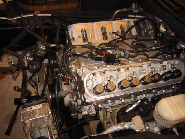
This picture should show exactly what you are looking at in your engine bay now. The cam is sitting there, waiting to be yanked out now. Before we remove the cam, make sure of the following: - All 16 lifters should still be uninstalled at this point. If for some reason you reinstalled them, remove them again - Radiator should be out of the car, and the A/C condenser should be able to swing forwards/backwards and lift up at least a foot or so - You have the cam bolts threaded in good for use as grips to pull the cam out. NOTE, if you have your waterpump bolts handy, thread one or two of these in the end of the camshaft. The extra length will give you more leverage to pull the cam out and keep it level. Just don't forget what those bolts go to! |

|
Now, grip the bolts on the end of the cam, and gently start pulling the cam out. The key here is to be gentle with this part. The cam will need to be constantly spun as you are removing it. You need to envision what is going on inside the motor, your cam is basically going through a few holes that suspend it. Once you pull the cam out a bit, its going to drop down some and the lobes are going to be getting caught on the cam bearings in those "holes", which is where the gentle spinning and tugging comes into play. Whatever you do, don't force the cam if it feels like its caught, just keep turning until it wants to naturally slide out more with gentle force. Once the camshaft if 1/4 of the way out, use 2 hands and try to leverage the end of the cam to keep the whole camshaft even, rather than dragging it out of the engine. Once you support the cam with two hands you'll see its much easier to remove as its not getting caught on everything inside. Once the cam is 75% out, have a friend hold up or move the AC condenser slightly until you have just enough room to pull the cam out totally and set it aside. Note that the AC condenser lines are not designed to flex TOO much so only move it as far as you need to. |

|
Get your new cam out of the box, coat the whole thing with fresh motor oil, and transfer your 3 camgear bolts to the end of the new cam so again you have a handle to grip onto. The installation is the reverse of the removal, for the first 75% of the install make sure you support the camshaft with two hands and keep it as level as possible as you slide it in. Don't push it into the motor with much force at all, and spin it as needed. The last 25% of the cam install you can only do one handed, so just gently turn the cam, wiggle the cam, and apply light pressure to it until it goes totally into the motor like before. This process may take 5-10 minutes so don't rush it. Once in, re-install the cam retainer plate and its 4 10mm bolts. I usually put some locktite on the 4 bolts and the GM torque spec on them is 18lbft. |

|
Optional: If you purchased a new oil pump and/or a new chain, you'll need to complete this step. First, unbolt the 4 10mm bolts holding the oil pump to the engine block, making sure not to drop any into the oil pan. Next, grab a 10mm wrench and unbolt the pickup tube bolt...it holds the pickup tube to the oil pump. Once its loose, unthread it and remove it with your fingers making sure not to drop the bolt into the oil pan. Now grab the pump with one hand and with your other hand or a screwdriver, push the pickup tube downwards into the oil pump to separate it from the pump. Once its separated, pull the pump off the front of the engine crankshaft. You can now remove your old timing chain if you need to. Place the new chain over the cranksnout and let it droop down like before. Leave the oil pump off the car for now. End Optional |

|
This step is one of the KEY parts of the install. If you mess this part up, you risk major engine damage once you try to start the car up later on. However, we'll verify everything is right before we go further, so don't worry too much. The goal here is to get the cam gear back onto the front of the cam, with the chain in place. That part is easy enough, the hard part is getting the dots lined up. There is one dot on the face of the cam gear, and one dot on the front of the crank gear (behind the oil pump). Thread your old crankshaft bolt back into the crank and with a wrench, turn the crankshaft until you see the small black dot pointing straight up. See picture on the left for reference. Next, in your hand, orient cam gear so dot is on bottom and hold it up to the front of the cam....see the smaller 4th hole in the cam gear? That is where the cam alignment dowel goes in. Spin camshaft by hand so dowel looks like it'll line up with cam gear properly to align the dots. Put the timing chain on the crank gear, and then put it on the cam gear, holding the cam gear up with your hand to keep tension on the chain. CAREFULLY, try to get the camgear to seat on the front of the cam. if you don't get the hole and the dowel aligned just right, you're just going to push the cam back into the block. If you are having trouble aligning it up, try threading a cam bolt through the gear into the cam to grab it and line it up like that. Most likely you are going to have to keep moving the chain on the cam gear until you get the dots lined up just perfect, and you'll have to get lucky and have the cam oriented just perfect so the gear seats on like it should. If all this sounds complicated, just look at the picture on the left and make yours look exactly like that. :) Don't get mad if this part takes 20-30 minutes of trying until it all looks correct. Once its all together, make 100.000% sure the dots are lined up exactly. You cant be off by a few degrees due to the sproket/chain setup, you can be off by one tooth at the minimum so if you are off you'll see it. If it looks off a little bit, turn the crankshaft by hand again to see if the 2 dots do indeed line up when they are straight up and down...sometimes if your crankshaft is 5 degrees too far , the cam gear will look like its off 10 degrees or so and you'll think there's no way they'll line up exact...when in actuality you just needed to get the crankshaft straight up. Now bolt the cam gear to the cam using the old 3 10mm bolts, again, placing locktite on the threads. These should be torqued to 26lbft. |
|
|
Optional: If you removed your oil pump in the previous step, you'll need to do this to reinstall it Find your oil pump pickup tube O-ring, it may be brown or blue in color. It will either be inside the opening of your stock oil pump, or it'll still be on the snout of the pickup tube. If it was inside the oil pump, remove it and place it on the snout of the pickup tube...just seat it on there, don't force it down any more than it wants to go naturally. If you bought a new oil pump, get it out now and place your old pump aside. Now, push the pickup tube downwards with one hand, and with the other, try to line up the gear on the oil pump with the gear on the crankshaft and push it on. Again, this may take a few minutes to get the gears all lined up. Once the pump slides on, rotate it a little and try to line up the snout so it'll slip into the oil pump nice and centered. If you try to insert it off center, you run the risk of chewing up the o-ring which will mean you have very little oil pressure and have to tear all this apart to get back in here to replace it. You don't want that, so make sure you insert the pickup tube nice and centered. It shouldn't take much force at all to push it in. Once its in, apply locktite to the old pickup tube bolt and re-install it. The torque specs are about 9 lbft, so just tighten it with a small wrench so its snug but don't go crazy on it, as its a really small bolt and the threads will strip out with too much force. Apply locktite to the 4 10mm oil pump bolts and reinstall them, torqueing them to 18lbft. End Optional |

|
Now lets work on getting the front buttoned back up. Grab your timing cover and look at the hole in it...there is a big round seal that is pressed in from the front. Flip the timing cover over and lay it across some 2x4's or across a concrete step (like shown in the picture) so you have room for the seal to pop out and not hit anything. Next, grab the biggest flat head screwdriver you have, and use it as a punch by hitting it with a hammer to drive the seal out from behind. Move the screwdriver to different parts of the seal after each whack so you don't just press one side of it out. Again, the picture shows this process. You may have to hit the seal a lot and with much force to get the seal loose. Once it pops out, flip the timing cover over and lay your new seal in place as centered as you can get it. If you have a block of wood, lay it across the seal and hammer on it to try to seat the seal properly. If you don't have a block of wood, just start by trying to tap the seal in on all sides until it seats, and then give it a few good whacks until its totally seated. |

|
On the very bottom of the timing cover, there may be some silicone sealant remaining, and if so, remove it. Next apply a bead of hightemp RTV sealant across the bottom of the cover, from one end to the other, like shown in the picture. Now set the timing cover back in place on the front of the motor and start hand threading all the 10 bolts back into place, only turning each bolt in 5-6 threads worth for now. The timing cover needs to stay loose for now. |

|
NOTE:If you purchased an underdrive pulley, now is the time to install it, otherwise, use your stock pulley. Either way, the instructions are the same for install. Seat your pulley back onto the snout of the crankshaft as best you can by hand. If you purchased a longer crank bolt, start threading this in now and pull the pulley on about a 1/4 or 1/2 an inch and remove the longer bolt. Use your old stock crank pulley bolt to pull the pulley onto the crankshaft until the bolt seems to get impossible to turn. Grab your biggest torque wrench and attempt to torque that bolt down to 240lbft. I have always stopped at 200lbft on my installs and I've never had a problem, so if you can't hit 240 (which I never have), don't worry about it. Now, break the bolt free and remove it. Take your NEW crank pulley bolt and thread it in all the way by hand. Torque this bolt to 37lbft. Now, we need to stretch the bolt into place. Get your breaker bar and pipe extension, and try to turn the bolt 140degrees past where it is at now, keeping in mind the engine will be trying to turn some and those are degrees you can't count. Again, I always seem to get about 90-100 degrees worth (estimating, knowing what 90 degrees looks like) and leave it as is so don't worry about going crazy here. Once the pulley is installed, the timing cover should be nice and centered around it, so we can now tighten all 10 of those timing cover bolts. Torque them to 18lbft on the bolts you can get a torque wrench on, and just make the others you can't get the wrench on about as tight as those. Now reinstall your A/C pulley using a 15mm socket wrench. Reinstall the A/C belt at this time. |
|
Part 4 Complete Thats it for the cam/oilpump/timingcover/pulley swap. Lets get back to the heads now. |
|
Part 5: Installing the heads Time to complete: 2-4 hours |

|
Swap Coolant temp sensor and coolant plug to new heads. Your new heads are identical, so it doesn't matter which head you put the coolant temp sensor or coolant plug in. The Coolant temp sensor which is found on the exhaust side of what was the drivers side head can be unscrewed with a deep 19mm socket. If you have teflon tape or gel, put some on the threads and hand thread the coolant temp sensor in as far as it'll go by hand. Torque this to 15lbft. The Coolant plug is on the exhaust side of the old passenger side head, and goes in the exact same place as the coolant temp sensor did. This is the only thing that will differentiate the two heads from this point on in the install as they are otherwise the same. If you didn't buy new sparkplugs, swap the sparkplugs over now. If you bought NGK TR55's, leave them at stock gap, put some anti-seize on the threads and put the new plugs in. |

|
Now, place your lifters and lifter retainers back in place like they were when you removed them. Try to keep them oriented exactly like they were before you took them out. If you don't remember how they came out, don't worry, and just put them in however. Its not that big of a deal. The small centerbolt that holds each lifter retainer down is 10mm. Apply locktite to the threads and torque them to 106 lb INCHES, or about 8 lbft. DO NOT OVER TIGHTEN THESE, or you will strip the threads out. Inspect the engine block surface and you should see 2 dowels sticking up about 1/4" on each side of the engine, they are 1/2" in diameter. If you don't see these 2 dowels, inspect your old heads and see if they came off in them (which is very rare), and put them back in the block. Now, lay the headgaskets on the block. Each headgasket will say "This side up" and will also say "FRONT", make sure the "this side up" is up, and the "front" part is to the front......the two gaskets are unique, so make sure you do this part right! The gaskets will line up with the dowels discussed above. |
|
Now lay the heads on the block, setting them on the 2 dowels. Reattach anything you disconnected on the back of the heads earlier. NOTE, on my car, I never reattach the harness on the back of the passenger side head, nor do I remount my AIR bracket. The only key things to reattach are the black ground wire(s), those MUST be bolted down good. |
If using OEM GM headbolts:

|
Now, grab a socket wrench and lightly turn the bolts until they stop. Now for the very precice part. You need to get your torque wrench out now and fit it with a 3" extension and a 15mm socket.  Using the sequence illustrated above, torque all 10 15mm bolts to 22lb-ft. OPTIONAL: Safety check! One one side of the motor install 2 pushrods (one exhaust, one intake), the rocker pedestal, and two rockers...then turn the motor over by hand two full turns. While this method wont be exact, if the engine didn't stop when you were turning it you most likely installed the cam correctly. If it felt like it stopped at one point and wouldn't go further, chances are a piston is hitting a valve and you need to disassemble things and go back to the dot to dot part, OR, your cam is huge and the piston to valve clearance is ZERO (it'd take a really big cam for this to happen) Ok, now for a GREAT tip from Scott99Z. Take a felt tip marker and draw a horizontal line on the head of each bolt. This is very important. Now, using the sequence illustrated above, turn all 10 15mm bolts an additional 90 degrees using a large socket wrench and a lot of muscle. Try to get as close to 90 degrees as possible...you may have to do multiple turns of 30 degrees or 2 turns of 45 degrees. When done all the lines on the bolt heads should be totally vertical. Next, again using the sequence above, turn bolts 1 through 8 another 90 degrees. This will take an immense amount of effort...if you have a buddy helping both of you should turn the wrench simultaniously. These 8 bolts will now all have horizontal lines on them Using the sequence above, turn bolts 9 and 10 an additional 50 degrees. Again, this will take a lot of effort. 50 degrees should result in a diagonal line on the bolts Finally, using the sequence above, torque bolts 11 through 15 to 22 lb-ft. |
If using ARP headbolts:

|
Apply the moly lube that came with the ARP bolts to the threads, as well as under the head of the bolt and both sides of the washer. Only a light coating is needed. If you don't have the included moly lube, put some motor oil on the threads. Torque all 15mm bolts to 30lbft in the torque sequence above. OPTIONAL: Safety check! One one side of the motor install 2 pushrods (one exhaust, one intake), the rocker pedestal, and two rockers...then turn the motor over by hand two full turns. While this method wont be exact, if the engine didn't stop when you were turning it you most likely installed the cam correctly. If it felt like it stopped at one point and wouldn't go further, chances are a piston is hitting a valve and you need to disassemble things and go back to the dot to dot part, OR, your cam is huge and the piston to valve clearance is ZERO (it'd take a really big cam for this to happen) Do a second pass at 50lbft, and finally a 3rd at 70lbft. Finally install the 5 smaller ARP bolts and torque them to 22lbft. |
|
|
Insert all 16 pushrods (7.400" is probably needed unless you have highly milled heads or a small cam, in which 7.350" might be needed), place pedestal back on the head, apply locktite to all the rocker center bolts and reinstall all the rockers. Torque the rockers to 22lbft.
Now, using your 24mm socket wrench, turn the motor over by hand (should be difficult as you are now building compression) and make sure the motor turns over by hand a full 720 degrees, then turn it another 360 (doesnt have to be exact or anything). Go over all the rockers again with your wrench just to make sure they are all at 22-24'ish lbft. |
|
Part 5 Complete One more part to go and we're done, hang in there. |
|
Part 6: Reinstall everything else that was removed Time to complete: 2-4 hours |

|
First, make sure you can see a few things before we put the intake manifold on. Find the electrical connector that plugs into the back of the intake manifold, the little vacuum hose that plugs in right next to it, and then also make sure your PCV hoses are all in place back there
Next, install the coolant crossover X pipe (if still using the old 97-00 style intake manifold), the 4 double ended bolts should be torqued to 9ftlbs (106 INCH/lbs). Now, place the rear 4 8mm intake manifold bolts into the holes in the intake manifold (remember, the drivers side rearmost 2 bolts hold on a metal bracket that keeps the fuel rail from breaking off in a collision, so put this bracket back on if you removed it) and slide the intake manifold into place. Before you put it all the way back there, snake the brake booster line through the wires and make sure its got a clear path back to the brake booster. Then, reconnect the electrical connector and the mini-vacuum line that goes to the back as well. Now, try to get the intake manifold to seat properly on the heads. You'll know when it seats at it'll stick in place and feel solid. Now connect the rubber brake booster hose back to the brake booster and reinstall the hose clamp. Hand thread in the rest of the 10 bolts now. Once all 10 intake manifold bolts are hand threaded as far as they'll go, tighten them down with a wrench and then torque in the order shown in the picture on the left. You need to torque these down in a 2-pass fashion..the first pass, tighten to 44 INCH-lbs, then, on the 2nd pass torque them to 89 INCH-lbs. NOTE: These are inch pounds, NOT foot pounds!. Go ahead and sort out your wiring harness mess and reconnect the 8 fuel injectors, the EVAP solenoid connector (bright red plastic connector), reattach the evap hose to the brass fitting on the front of the drivers side of the manifold, and reconnect your PCV valve to the rubber grommet on the front of the passenger side of the manifold. The PVC line has a grounding strap that attaches to the front passenger side coolant pipe bolt stud...reconnect this. |
|
|
Get under the front of the car and grab the steering rack and try to pull it back over into place. You'll need to aim the drivers side tierod through the opening in the side of the engine bay so it can be reconnected to the suspension in the wheel well. Push the drivers side bushing on the rack into place on the crossmember, and start the bolt temporarily (just stick it through, you don't need the nut on yet). Now try to press the passenger's side bushing down into the bracket on the crossmember...this may take some work with the rubber hammer, just make sure the rubber bushing doesn't get hung up. Some lube of some sort may ease the process. Once its in, get that bolt started too and go ahead and tighten the passenger side bolt and nut down to 74 lbft. Now, reconnect the tierod ends in the wheel well with an 18mm wrench. Torque this to 35lbft. Align your rotors so they look like they are aimed straight ahead, just as you left them when you shut the car off (or in whatever direction you left them when you locked the steering wheel). Reconnect your power steering intermediate shaft to the power steering gear stubby shaft. This should slide on from the side. If yours required hammering to remove, it may require hammering to reinstall, otherwise it may just go on with ease. If its not going on easily, your wheels (rotors) may be turned a few degrees off so try nudging them a little in each direction until the shaft slides on. Apply locktite to the shaft bolt and torque it to 25lbft. For now, leave the drivers side rack bolt loose. |
|
|
Now, stab your oil dipstick tube back into place (the bolt hole in the header will give you a clue as to which pipes to go between). This part may be easier if somebody gets under the car and feels around for the hole it goes in and guides it by hand. The process can take 5-10 minutes of searching until the tube goes in just right. Once lined up with the hole give it a good push and it'll snap in. Then reattach the holddown bolt to the exhaust manifold/header. |
|
|
From the top of the engine bay, drop your power steering pump/pulley/bracket/hoses assembly we removed earlier roughly back into place, making sure your powersteering cooler lines get out back in front of the crossmember. Get under the car and bolt the 2 cooler lines back into place held down by the two black plastic brackets. Now, reconnect the two hoses to the power steering rack. They should be different sizes so you can't put them on wrong...just make SURE you hand thread them far enough in as you really don't want to cross thread these! Use your 18mm flair nut wrench to snug them down. From underneath the car, remove your drivers side power steering rack bolt (should still be loose) and place the ABS block bracket back into place. Its held on with 4 smaller bolts and then the one big rack bolt. Again, torque the big rack bolt to 74lbft. The smaller bolts just need to be snugged down, nothing critical there. While you are under here, reconnect the magnasteer electrical connection to the rack. Reinstall your swaybar. First bolt it into place by bolting the two bushings/brackets to the frame. The rubber bushings have a groove/bump on each one to show you which way the bracket fits on them. Bolt them to the chassis and torque them to 43lbft. Then reconnect the swaybar endlinks using the torx bit from earlier and an 18mm wrench. Make these as tight as you can get them, the book calls for 53lbft but you can't use a torque wrench here since you need to grab the torx part AND the nut at the same time. Back up in the engine bay, re-bolt the bracket to the drivers side head. NOTE: You can leave out the bolt at the bottom that is the big pain in the butt if you want, as 3 big bolts are more than enough to bolt this bracket onto the engine. You'll need your open ended 15mm wrench to reinstall it, turning each 15mm bolt a few turns at a time making sure you tighten all the bolts simultaneously. |
|
|
Grab a friend again and work the radiator/fan assembly back into place, again making sure you don't snag any wires. Once in place, try to set the AC condensor tabs back into the slots on the front of the radiator so they are attached. Reinstall the waterpump now, using new gaskets if you bought them. Hand thread in all 6 waterpump bolts as far as you can, then finish the job off with a wrench. Torque the waterpump bolts in a 2 pass sequence, first to 11lbft, then do a second pass and tighten them to 22lbft. Reconnect the 4 hoses that go to the water pump, 2 big ones that go to the radiator, and 2 medium ones that go to the heater core. Work the metal hose clamps back into place. Reconnect your alternator to the drivers side bracket with the 2 15mm bolts you removed earlier. Reconnect the power cable on the back using a 13mm socket and place the rubber boot back over the nut. Reconnect the electrical weatherpack connector to the alternator. Route the drivebelt back into place. It will only route properly one way, so make sure you get it right. There should be a reference picture of the belt routing in the engine bay. Using a 15mm wrench on the tensioner, loosen the tensioner and slide the belt on. Finally, underneath the front of the car, reconnect the 2 connections for the electric cooling fans and re-secure the wiring harness to the fan shroud using the plastic clips that are attached to the fan shroud. Make sure you have closed the radiator drain valve as well. |
|
|
Reinstall your valve covers. 99+ years use 4 8mm center bolts while 97-98 models use perimiter bolts. The valve covers use a rubber gasket so torque isn't important here, the GM book calls for about 8lbft on the bolts, which means just make them tight enough until they compress the gaskets to ensure a tight fit. Once the valve covers are on, on the drivers side you need to push the PCV hose tube into the grommet on the rear of the valve cover, and on the passenger side you need to connect the rubber PCV boot to the rear of the valve cover. Now reinstall your coil packs. NOTE: I leave off the back hard to get to coil pack rail bolts ('99 and up only) to make rail removal easier in the future. Reinstall your AIR tubes. You'll need to use NEW air tube gaskets and again you need to hand thread in the 10mm bolts to the exhaust manifolds/headers to ensure you don't crossthread them. The GM spec on those bolts is 15lbft, but I just make 'em tight (you'll get good at estimating torque values so you don't have to use the torque wrench on all the non-critical bolts). On the drivers side, make sure you reconnect the rubber hose to the metal AIR tube. Reconnect all 8 of your spark plug wires, the should snap once on the spark plug end, and twice on the coil pack end. Now, snap your metal fuel line back onto the fuel rail connection by pushing it on until it clicks. Make sure its firmly attached by giving it a firm tug. |
|
|
Re-bolt the 3 10mm bolts on to hold your throttle body to the intake manifold. These should torqued to 8lbft. Reconnect the electrical connections going to the throttlebody now. Reconnect your coolant lines (if you don't have a TB bypass installed) to the throttlebody and connect the coolant line back to the radiator now as well. While you are there, reconnect the final rubber line to your radiator, this one should go to your coolant overflow fill tank. Once the two small lines are reconnected to the radiator, reinstall your radiator shroud. It's held on by 4 10mm bolts, just make them snug. Now reinstall your maf/airbridge/airfilter assembly you removed earlier and reconnect the MAF and air intake electrical connectors. |

|
Fill coolant reservoir until it doesnt seem to keep going down. It should take one full coolant bottle of DEXCOOL, and about 1.2 full coolant bottles of water. Reconnect battery. Fill powersteering reservoir with fluid. Unlock steering wheel using your key (power should be back on now) and rotate steeringwheel lock to lock (meaning, as far as it'll go in each direction) 15-20 times and keep filling powersteering reservoir as needed, keeping in mind its not supposed to be FULL, just up to the line that is on the power steering dipstick. Check your oil level at this time and add any if needed. |
|
Part 6 Complete Now lets get ready to fire this sucker up. |
|
The big test! Starting it all up Time to complete: 30 minutes |

|
First and foremost, look over EVERYWHERE in your engine bay for stuff that is disconnected. Make sure no fluids are hitting the floor or dripping, make sure there are no electrical connections unconnected, etc. Take 15-20 minutes looking for anything, double checking everything. Take the coolant fill cap off so we can watch the coolant level and let air bubbles work themselves out. Now, make sure the coil packs are disconnected from the wiring harness (leave the spark plug wires all connected, just disconnect the wiring harness going to the packs), and get in the car. Insert the key and turn the motor over for 4 seconds...it wont start as long as you've disconnected the coil pack wires. If the car turned over fine, connect the coil pack wires. Now, PREPARE YOURSELF. There are a few things you need to know before you turn the key: 1) The engine is going to be REALLY noisy for about 4-5 seconds. This is because the lifters need to pump up with oil. 2) Your oil pressure needs to be watched like a hawk on this first startup. It should take 3-5 seconds to come up to 30-50psi at idle. 3) Smoke will start coming out of your engine bay like mad for the first 5 minutes. This is normal and is just coolant/oil/grease/fingerprints burning off all the stuff you touched. ...Now...Turn the key being sure to keep an eye on the oil pressure guage. Make SURE oil pressure comes up within 5 seconds (it'll take a few seconds since the motor has been apart and you may have swapped the oil pump) and if it doesn't, shut the car off. The car should idle really poorly (depending on how big you went with the cam), and rpms will fluctuate a lot. If it keeps trying to die, give it 5% throttle just to keep it idling and slowly back the throttle off until it knows how to stay alive on its own. If all is going well, let the car idle up to full temperature, making sure to constantly watch the coolant reservoir tank and refill as necessary. While its idling move the powersteering back and forth lock to lock 15-20 more times and make sure the power steering fluid is topped up if needed. once car reaches full temp, shut it off. Install the coolant fill cap, and power steering reservoir cap. Reinstall front wheels, jack the car up, remove jackstands and lower the car. Tighten the front lugnuts to 100lbft. You are ready for your test drive! For the first day, cruise around in the car as long as you like and get the car nice and hot, full operating temperature. Don't take the RPMS over 4000 until the springs have a chance to cool overnight. The next day you can take the car to redline, just remember that HIGH rpms on cold valve springs is bad, make sure your engine is warm before you beat on your car from now on. Stiffer springs need a little more care in this area. Final Notes: - After you have 100 miles on it, its probably good to go change the oil, re-check the coolant level and power steering level, and enjoy! - Remember, with stiffer valve springs it becomes more important to make sure your car is fully warmed up before you take it to high rpms, as the springs are more brittle and prone to breaking when cold. - If you have a check engine light, hold the options button on the DIC and simultaniously press the fuel button 4 times, it will then read off the codes. A common code at this point is P0300, and may happen from time to time when idling depending on the size of your camshaft. - Your car will try to die once you rev it up some and let off. this will make it difficult to drive at first, but after 100-200 miles of city driving it will learn itself out. If it doesn't, programming may be able to fix the issue or you can drill a small hole in your throttlebody blade to let more air in at idle. - More valvetrain noise is normal, depending on the ramp rates your new cam has. More agressive cams WILL make the engine sound like a sewing machine, especially when you are inside the car driving with the windows up and radio off. This is normal. |
|
End of install Congrats, you've finished the install! |