
| Tools Needed: |
- 10mm socket, socket wrench - Recommended: 10mm gear wrench - 15mm wrench - 3" socket extension - Flathead screwdriver - Torque wrench - Drill with 1/16" and 3/16" bits - 3/16" Allen wrench - Pliers - Bucket - Car ramps - Crimper/wire stripper tool - Recommended: Voltmeter - Recommended: Soldering iron/solder |
| Parts you will need: |
Parts: - Meziere LS1 Street pump available from 
- SBC style thermostat (160 or 185 degree recommended) available from
- Crimp-on eyelet wire connector - 16-18 gauge wire tap connector - 4-5' of 16-18 gauge stranded wire (2' of black, 2' of red is optimal) - 4-5' of 18-20 gauge stranded wire - Recommended: Automotive Relay (I used a Borg Warner R3151 Coolant Fan Relay) - Recommended: Crimp on quick-disconnects (for relay) - Recommended: Heat shrink tubing - Butt Connectors if you are not going to be soldering/heatshrinking Bolts/gaskets: - Recommended: 2 Water Pump gaskets GMPN 12553617 Supplies: - Jug of DexCool compatible coolant - RTV Silicon Sealant/Gasket Maker |
|
For years talk of electric water
pumps had been circulating through the LS1 community, and finally Meziere has
delivered. Whether you are a hard core drag racer who wants to just cool the
car in the pits and staging lanes, an enthusiast who's itching for more power
from his heads/cam car, or just a basic bolt on type of guy, an electric water
pump is probably for you. In this install I'll go through a full walkthrough of installing a Meziere Street Electric pump on a '97-'04 C5 Corvette. It is very important to note that there are an unlimited number of ways to wire up the electrics to this pump, and in this document I will only provide a few options. My personal recommendation is to use an automotive relay and trigger it off the fuel pump trigger wire. If an additional need of being able to turn the pump on with the car off is required, then a switch and some diodes should be added to this setup. I will start out the install by doing 90% of the wiring first so that the install can be broken up into 2 sessions if needed without the car being down (incase it is a daily driver). |
 The parts needed
|
 Closer shot
of the pump Closer shot
of the pump
|
 |
The first part of this job is figuring out how you want to do the wiring. The
basic idea is obviously to get power to the pump, but how you do this is really
up to you. I will show you the method that I personally used, and give you
hints as to optional ways to do things. Everybody will have their own personal
preference...some like to solder/heat shrink everything, some are ok with butt
connectors, some are ok with posilocks, and some are even ok with wirenuts and
tape (!). I personally recommend you solder/heatshrink everything, but if you
can't solder than it is perfectly acceptable to buy some butt connectors or
posilocks from the autoparts store and do things that way.
Aside from the nitty gritty specifics of the wire connections themselves, you'll also have to decide if you want to use a relay or not. If you do not use a relay, you will need to tap your wire into an already existing wire and pull the pump power off of that. The downside to this is that you will then be pulling more power off a wire than that wire carries stock. Will this be an issue? Probably not, but you may end up blowing whatever fuse that wire is on at an inopportune time and that will not be fun. The more "OEM" option is to use an additional relay. A relay is like an electronically controlled light switch, it doesn't take much power to switch on and off so whatever wire you tap into will not have to supply very much energy to switch it, meaning you will not have to worry about blowing fuses on another circuit in the car. You'll then supply a clean supply of power straight off the battery to go to the pump (through the relay), and the relay will switch this connection on and off to the pump. This is the method I recommend, and it is what I will detail in this install. |
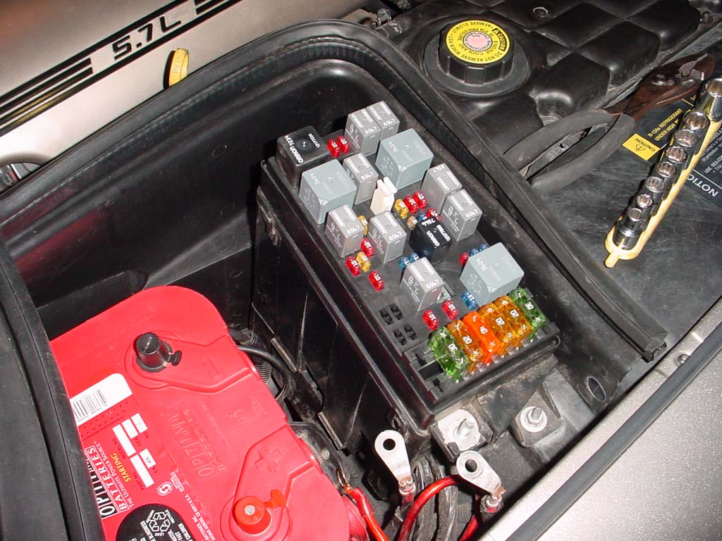 |
Let's get started. Pop open the hood and find the fuse box that is right in front of the battery. Unscrew the thumbscrew and remove the lid to the fuse box. Around the edge of the fuse box, there are 4 clips...2 on each side. Unclip all 4 and separate the top of the fuse box from the base, and pull it up as much as you can. The wires will be very tight in there, so you won't be able to pull things up very much. |
 |
This is the view of wires you should have under your fuse box, looking at the
rear drivers side of the fuse box. What we need from here is a "trigger wire",
or, a wire to switch our relay on and off. The wire I recommend is the large
gray wire labeled in the picture. This gray wire will be "on" when the fuel
pump is running. It is also fairly easy to get to as it is on the very edge of
the back of the fuse box.
|
 |
Using a wire tap, connect a 16-22 gauge wire to the grey (or pink if you chose
to do that) wire shown above. This new wire you tapped on will be your trigger
wire for the relay, and should be long enough to make it to wherever you will
mount your relay. If you haven't decided where you will be mounting your relay,
just leave a few feet attached for now. I now recommend you test this trigger wire using a volt meter or a 12v LED. Turn the key on and the volt meter should read 12-13V for 1-3 seconds and then shut off at the same time the fuel pump shuts off (you can hear the fuel pump). Assuming all is well, you can proceed! Run the newly added trigger wire down through the base of the fuse box and out the back side of it and pull it through. Once you pull the wire through the bottom, you can then reattach the top of the fuse box and re-attach the lid and thumbscrew. We're done inside there!
|
 |
Next we need to run a ground wire for the relay switch circuit. Cut off a
section of wire (black preferred!) that can run from wherever you will mount
your relay to a grounding point on the C5 frame. The grounding point I used is
right by the passengers side hood strut. You'll see a bolt there holding down
some other wires. Crimp an eyelet crimp connector on the end of the wire, and
bolt the eyelet down. Run the wire back up to where you will mount the relay,
making sure it will not be getting tangled up in anything. You can run the wire
pretty stealthily back to the fuse box by going under the coolant reservoir, as
there is already a wiring conduit down there.
|
 |
Now for the 3rd wire, the hot wire. This is the wire that will supply the water
pump with power (via the relay). Right on the side of the fuse box is a stud
with wires attached to it. Once again, use a crimped on eyelet and enough wire
to get you to your relay mounting point and run the wire. BE CAREFUL, as this
wire will be electrically charged if you have not disconnected your battery! Once one end is bolted to the positive battery terminal on the fuse box, run the other end to your relay mounting point.
|
 |
Now that we've got the wires run, lets figure out this whole relay thing. On
the bottom of the relay are 4 terminals, making up 2 different circuits. One
circuit is the "switch", and it doesn't require much power, and one circuit is
for the accessory...in this case, a waterpump.
Now, at this point in the install you should have 3 total wires going to wherever you chose to mount your relay. The wires you should have are: - 1 Trigger wire that is tapped into the gray (or pink) wire in the fuse box - 1 Ground wire that is bolted to the frame - 1 Hot wire that is bolted to the positive battery terminal Once you finalize the relay mounting point (I mounted mine to the large black shield around the battery/fuse box), trim the 3 wires to the proper length, leaving a 1-3" to spare as slack. Strip the ends of those 3 wires and crimp on a quick disconnect. You can then slide the connectors onto the relay in the proper locations. The Hot wire goes to the #30 terminal, the Trigger goes to the #85 terminal, and the ground goes to the #86 terminal. #87 will stay empty for now. |
 |
This is what you should have at this point...a relay with 3 wires going to it.
We'll add the fourth wire at the end of the install so don't worry about it
just yet. Once you have gotten to this point, the car is still 100% drivable so it is a good stopping point if you are running out of time and need to drive the car. Once you go on with the instructions, the car will be down until you are 100% done. |
 |
Wiring DiagramFor reference, the wiring that I talk about above is shown in this schematic on the left. This is what I'll call the "OEM style" install....a new relay that switches a fused device (the water pump). If you want the job done simple, but "right", this is probably the way you should do it.Just about any automotive relay should do, but it'll be easiest if you get one that can be easily mounted somewhere. |
 |
Alternative Wiring (Manual Override Switch Added)To add on to the original wiring, when using a relay it is VERY easy to add in a manual override switch as shown with the new green lines in the diagram. The way this wiring diagram shows it wired up, the water pump will ALWAYS run when the engine is running, PLUS it will run any time the switch is turned on. The diodes are required, not just recommended. Diodes are a "one way street" for electricity and having them there will keep the juice from your switch getting into the fuse box and powering an accessory (whatever wire you tapped into), and likewise, it will keep power from flowing back up into your switch wiring when the car is running and pump is on.I expect that the green wires in the diagram will be in the car (you can find a 12V source in there) and then you'll run it through the firewall and to your trigger wire on the relay. You could however, just mount the switch in the engine bay since chances are, you'll probably only be doing the manual override when you're in the pits and the hood will be up anyways. |
 |
Alternative Wiring (Simple Wiring)If you want absolutely the SIMPLEST wiring possible, you don't *have* to use a relay. I don't specifically recommend this method, however it most likely will work just fine. In GM wiring, the fuse comes before the relay. What does this mean for you? Well, if you just simply tap the water pump wire into an existing wire, you'll be also pulling power through an already existing fuse and could exceed it's rated capacity. It'd not be good if you're cruising down the road and all of a sudden you lose your fuel pump / water pump fuse because you were running 2 things off of it instead of just one.If you understand the above and are fine with that, then the diagram on the left will show you how to wire it. No relay needed, and the wiring is VERY simple. I personally have tapped into a large pink wire coming off an IGN relay, and it worked fine, but for my own personal car I used a relay as shown above. Adding a switch to this setup is a little more messy. |
 |
Start by driving the car up on ramps and shutting it off. If the car has been running for a long time and is fully warmed up, let it sit for 30 minutes to an hour to let the coolant pressure go down. Once cooled, remove the coolant reservoir cap and get under the car. Find the drainage valve on the passenger side of the radiator. Using 1/4" drive ratchet, or a large flat blade screwdriver, twist the drain valve counter clockwise and have a bucket ready to catch the coolant coming from the spout. |
 |
Now disconnect all the sensor plugs going into the airbridge/maf and throttle
body. On 97-00 cars there are 4, one in the MAF, one on the air bridge, and 2
on the throttle body (one on each side). On 01-04 cars there are 3, one in the
maf, and the 2 on the throttle body. There will also be a rubber air hose
going to your air box or filter somewhere, and that will need to be disconnected. If you have a blackwing air filter or similar, loosen the clamp that holds the accordion shaped intake tube to the throttle body, and pull the whole Maf/Airbridge/air filter assembly off the car and set it aside. If you have a stock air box, or something like a ram air box, just remove the airbridge and throttle body/airbridge coupler. You can leave the air box in place if you wish. For other intake setups not listed, do something similar. We just need to be able to have access to the water pump, so use your judgment and remove only what is necessary on your specific setup. |
 |
At this time, we also need to disconnect the black rubber vent tube from the
rear passenger side of the throttle body. You can leave the other end connected
to the valve cover. If you do not have a coolant bypass installed, there will be 2 coolant hoses going to the throttle body. One goes into the drivers side, and one comes out the passengers side. On the drivers side, you need use pliers to compress and slide the hose clamp down the engine end of the hose, and then pull the hose off the engine's metal coolant line. If this line feels stuck, try twisting it, or prying at the end of it with a flathead screw driver to break the tension. On the passenger's side, follow the hose out of the throttle body until you see it go into the coolant reservoir. Using pliers, compress the hose clamp and slide it down a few inches, then pull the hose off the coolant overflow tank. You can now remove the 3 10mm bolts that hold the throttle body to the intake manifold, and set the whole throttle body/hose assembly aside. |
 |
Using a 15mm wrench on the center bolt through the tensioner pulley, push the tensioner towards the drivers side of the engine to remove tension from the main drive belt. With tension removed, slide the belt off the main water pump pulley (or any other pulley) and then release the tensioner and remove the belt from the vehicle. |
 |
There are 4 hoses we now need to disconnect from the water pump. First remove
the large main outlet hose that is near the top of the water pump using pliers
to compress the hose clamp. Next, remove the large inlet hose that is towards
the bottom passenger side of the pump. This hose, when removed, will probably
spill some coolant, so move your bucket back about 12-14" now from where it was
when you drained the radiator. Bend both of these disconnected hoses out of the
way for now. With the two main hoses out of the way, you should be able to get your pliers in and compress the clamps on the final 2 smaller hoses (they are for the car's heater core) and then pull both of those hoses off. These too will spill lots of coolant onto the ground. Now that all 4 hoses are disconnected, get a 15mm socket and 3" extension and unbolt the 2 15mm bolts holding the tensioner to the water pump. |
 |
This is what the removed tensioner looks like. |
 |
We're now ready to pull the water pump off the engine block. All that is left
is to locate the 6 10mm bolts to remove, and remove them using a 10mm socket
and 3" extension, or a 10mm deep socket. Back all 6 of them out about a 1/4"
first, and then start removing them one by one. The bottom drivers side bolt
will require a 10mm wrench (socket wrench HIGHLY recommended here) to loosen,
and it will not be able to be totally removed from the hole as a pulley is in
the way...this is ok.
Once all 6 bolts are removed the pump can be pulled right off, and you'll hear a nice splash of coolant hit the ground. Sometimes the pump will feel like it is still stuck on the block on '98 model cars, so it may require a little bit of prying to break it free. Once it is off, set it aside so we can work on it. |
 |
This is now what your engine bay should look like. The large metal cover that was behind the water pump is the timing cover, which is what covers your cam gears, timing chain, and camshaft. |
 |
Now, lets get to work on getting the new pump ready for install. The new
Meziere water pump does not come with an inlet so we will need to remove the
stock outlet spout from the stock water pump. It is held on by 2 10mm bolts. Once removed, pull the whole inlet spout up and out of the stock waterpump. |
 |
You can now see that inside the inlet is where the stock thermostat resides. We do not have any use for this stock thermostat in the meziere pump, and it must be removed. To remove the thermostat, you will need to press down with a lot of force on the 2 arms that come off the thermostat and slot into the 2 posts sticking up from the inlet. Once you are pressing down, you then need to rotate the whole thermostat until the 2 arms are out of the slots in the posts. It is hard to explain in words, so the picture on the left may help. |
 |
Now that the old thermostat is removed, let's switch tasks and get out your NEW
thermostat. The Meziere pump uses an old small block chevy style thermostat to
control coolant flow. To keep the electric mechanism of the pump healthy, we
need to drill some small holes in the thermostat to keep coolant flowing even
when the thermostat is shut. This will also help get the air out of the system
once we fill the radiator with coolant later. Start out using a 1/16" drill and drill into the thermostat away from the 2 support arms on the thermostat. Once you've got the two small holes drilled, go back in with a 3/16" drill bit and enlarge the two holes. Use a screwdriver or sand paper to break off any metal splinters that you may have created during the drilling. |
 |
If your meziere pump arrived with the outlet spout already installed, now is the
time to unscrew it. If you grab it tightly with your fist, you should be able
to sloooowly turn it loose and remove it. Under here is where the new
thermostat goes. Now place the thermostat into the opening with the spring on the thermostat going down into the pump. Reinstall the outlet spout and tighten as tight as you can get with your hand. |
 |
Take your removed stock inlet spout from the stock pump, and check the back of
it to make sure the rubber O-ring is still installed. Using the 2 supplied hex
bolts and washers, bolt the stock inlet to the meziere water pump and tighten
using a 3/16" hex key.
Now is also a good time to thread in the two heater hose spouts into the passengers side of the meziere water pump. The larger of the two goes towards the front of the pump. Meziere recommends using a small bead of RTV around these fittings before you thread them in. |
 |
On the C5, the wires will need to be going back to the passengers side, but as
you'll notice the wires come out on the drivers side of the pump itself.
Meziere includes a small metal tab that goes under one of the bolt heads, and
you can use that to help you route the wire. I suggest at this time that you
run the wire over the top of the pump and mock it up with a bolt and the tab right now,
as shown in the picture. It is much easier to see how this routes while the
pump is still off the car, so its better to do this now rather than later
|
 |
Before we attempt to install the new pump, I recommend sticking some RTV silicon on the gaskets and sticking them to the back of the pump, and then putting a few bolts in the holes to make sure the gaskets stay aligned properly. This will make it a lot easier to get the gaskets into position once you are trying to bolt it in place. |
 |
The pump is now ready for installation. Grab the pump and try to put it in
place, making sure that you have the one bolt on the bottom drivers side in
place beforehand (as you won't be able to put it in later due to the pulley). I
suggest sliding the drivers side down in first, then follow with the passengers
side. This process may take a few minutes of wrestling.
Once the pump has been worked in as close as you can get it, you may have found that it just simply wouldn't mate up to the block. This may be because the throttle body flange on your intake manifold is interfering with the pump itself, or it could be because the pump is interfering with the power steering bracket on the drivers side head. |
 |
If the pump is interfering with the intake manifold, you'll need to grind a
small portion off the intake where the interference is occurring. I did this
using a dremmel with the sanding barrel installed, and grinded about 50
thousandths of an inch off the corner of the throttle body flange. This in total
took about 15 seconds at medium speed, working my way back and forth on the
corner.
If you do not have a dremmel, a razor or a file may do the trick. If the pump is interfering with the power steering bracket, a dremmel or file will take care of the issue. I recommend grinding the bracket, and not the pump. |
 |
Re-fit the intake and make sure you now have enough clearance. Now hand thread
in all 6 bolts as far as you can with your fingers making sure that each bolt
is in fact going through the water pump gasket as it should. The bolt install
process may require that you lift/support/wiggle the water pump before you can
get all 6 started, but it is very important you do not just wrench these bolts
in right from the start. The water pump bolts are not bolts that you want to
cross thread! Make sure if you ended up using the wire hold down tab that
meziere provides that you have installed it under one of the bolt heads. Once all 6 bolts are started, go ahead and use a 10mm socket wrench and 10mm wrench to tighten all the bolts down. Using a torque wrench, torque all 6 to 11lb/ft in one pass, and then do a second pass at 22lb/ft. The 6th bolt that you can't get a socket wrench on will just have to be tightened with a normal wrench to what feels like 22lb/ft to you. |
 |
It is now time to reconnect the 4 water pump hoses. Reconnect the 2 smaller
heater hoses from back to front, and reinstall the hose clamps to hold the
hoses in place. Next reconnect the two large hoses and reinstall their hose
clamps. Now install the stock belt tensioner to the water pump using the stock 15mm bolts and torque these to 37lb/ft. Once the tensioner is installed, re-install the drive belt using the routing diagram in the engine bay. I suggest you put the belt on all pulleys except for the water pump pulley, then put the wrench on the tensioner and reduce tension, then slide the remaining part of the belt onto the waterpump. |
 |
Re-bolt on the throttle body using the 3 10mm bolts you removed earlier and
reconnect the rubber hose coming from the valve cover to the top rear of the
throttle body. Next, reconnect both coolant hoses (if you didn't have a bypass)
to their corresponding locations, making sure to get the hose clamps on
properly. Grab your intake/maf/coupler assembly and slide the coupler onto the throttle body so it is nice and snug, and push the air bridge down onto the pegs on the radiator support to secure it. Tighten the large band clamp at the throttle body using a flat head screwdriver. Now we can reconnect the electrical connections we disconnected earlier. Each sensor has a unique connector, so you can not reconnect these incorrectly. |
 |
It's time to fill the car back up with coolant now! Before you do anything, get
under the car and make sure the radiator drain valve is shut tight. The last
thing you want to do is start pouring coolant in and see it coming right back
out at the bottom. Pour in 1 full jug of Dex-Cool compatible coolant, and then follow up with as much water as you can pour into the radiator overflow tank. For now, leave the coolant reservoir cap off. |
 |
The final steps of the install are to finally hook up the 2 wires coming off
the meziere pump. Plug the weatherpack connector into the plug and see how much
spare wire you have. We'll need to get the blue wire coming off the pigtail
over to the relay, and the black wire will need to get to a grounding point. Chances are, the pump's wires are too short to make it to where you'd like to go, so you may need to extend the wires some. If this is the case, you can use posilocks, butt connectors, or you can solder an extension on. To solder, you strip an end of each wire, interleave the strands of wire, and twist them together...then, apply solder to the connection and heat shrink it. This is the best way to extend a wire, however the other methods will suffice. |
 |
Once you've extended the wires, cut and crimp on an eyelet connector to the extended black wire and ground it to the frame (or any other ground point). I chose to use the same ground point we used earlier in the install, and covered both of the new ground wires with a piece of 1/4" plastic wire loom to make the install look OEM. |
 |
Now run the extended BLUE wire off the pump under the big plastic shield and
into the fuse box area. Once in there, cut it to length, crimp on a quick
disconnect (then solder it if you want), and plug this in to the final
remaining terminal on the relay...#87. You can then mount the relay in its position. That is it with the wiring! |
 |
Finally, the pump is ready to test. Put the key into the ignition and turn it
to the ON position but do not start the car. You should now hear the water pump
whirring away for a few seconds and then shut off. I recommend you make SURE
you can hear the pump for that few seconds, it may help to have a friend
listen. Once you are sure the pump is all wired up and running properly, start the engine. Before you drive anywhere, let the car come up to full operating temperature and make sure that the car does not overheat. It should stop moving up about 180-190 degrees on the gauge, and sit there. If the car starts to overheat, shut it off and let it sit for 20 minutes then carefully remove the coolant fill cap and add water if needed and restart the process. Eventually all air bubbles will get worked out through enough heating cycles and you can then drive the vehicle. |
 |
Once the coolant system has all the air worked out, and the car maintains a
temperature at idle, you're set to enjoy your new mod! Thunder Racing has
tested this mod on several test cars, and the average rwhp gains seem to be
around 6-7rwhp. An actual dyno graph is shown to the left. Once again I'd like to thank
Meziere and
for helping to make this writeup possible.
|